

ALLISTAIR COTA
DESIGN PORTFOLIO
CNC Milling Machine
For the Mechanical Engineering Design course, my team was tasked with designing an entry level industrial grade CNC milling machine. We decided to design a machine that would cater specifically to the needs of small auto shops building custom automotive parts like engine blocks. This led to us designing a 5-Axis CNC milling machine, with linear motion in the X, Y, and Z axes, along with rotation about the X and Y axes.
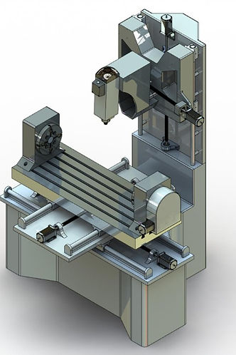
Rendering of the final design.

Y Rotation of the spindle is achieved through a pivoting lead screw mechanism.
Candidate Selection
After developing an engineering specification for the design, the team decided to work in pairs to develop candidate designs. The candidate design that I worked on with another team member was eventually selected as the final design. The more heavily weighted criteria for the selection process included the functionality as well as the precision of the machine.
Key Design Features
Unlike existing 5 Axis CNC machines, where rotation about the X axis is achieved by rotating both the workpiece and the work table, our designed used chucks similar to lathe chucks placed on the worktable that could clamp the workpiece and rotate it when needed. This reduces the torque requirement for the motor as the work table does not need to be rotated.
Another unique feature was the rotation of the spindle about the Y axis using a lead screw driven inverted slider crank mechanism which results in a high resolution in terms of Y rotation.
Detailed Design Components
Bearings, couplings, motors, and fasteners were also chosen for the final detailed design. Angular roller bearings were used on all lead screws as they can resist both radial and axial forces, while linear bearings were used along the X, Y, and Z support rails in order support motion along those axes even during high speed and load requirements.
Engineering Drawings
Engineering drawings of all the parts and sub-assemblies in the design were produced and included in the final report, in order to fully explain and communicate the design features. Furthermore, exploded views of the full assembly and sub-assemblies were produced to show the assembly process of the machine.
Minimizing Cost
All the design decisions were made to meet the objective of reducing the selling price of the machine. The final design was estimated to cost $18,179, well below the industry standard of $50,000 - $70,000 for 5 Axis machines of similar footprint and functionality.
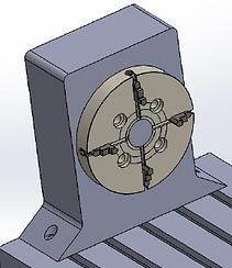
Assembly of the workpiece chuck.
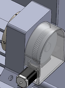
Worm gear driving the X rotation chuck.
 CNC Milling MachineRendering of the final design. |  CNC Milling MachineRight view. |  X Rotation Chuck |
|---|---|---|
 X Rotation ChuckWorm gear drive increases torque from the stepper motor to the chuck. |  Rotating Spindle MechanismAnticlockwise rotation of the lead screw results in anticlockwise rotation of the spindle. |  Spindle Assembly Exploded View |
Team
-
Samson Chiu
-
Allistair Cota
-
Alain Cubric
-
Syed Saad Hussain
-
Ashmith Muppalla
-
Jonathan Swiecki
