
ALLISTAIR COTA
DESIGN PORTFOLIO

Reduction Gearbox
For this Mechanical Engineering Design dissection, my team was given an industrial quality right-angled reduction gearbox to examine and use as an inspiration for developing a new design for a reduction gearbox. The requirements for the new design included tolerating high speed input and high torque output, as well as tolerating external axial and transverse forces at both input and output. A number of constraints also had to be met, including achieving the same 30:1 gear ratio as the original design, keeping the same dimensions for the mounting flange and input and output shafts, and roughly maintaining the same total volume from the old design.
Reverted Gear Train
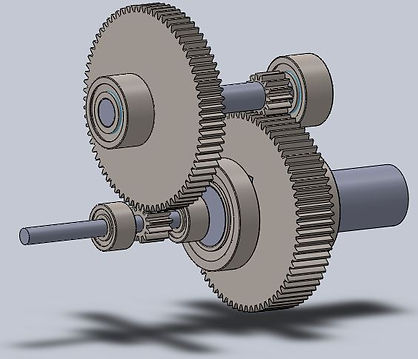
We decided to utilize a reverted gear train in the new design, which is a compound gear train with both the input and output shafts aligned collinearly. Using gear equations relating the gear ratio to the number of teeth, module and pitch circle diameter that were taught to us in the Kinematics and Dynamics of Machines course, the properties for each gear were determined such that the 30:1 gear ratio was maintained and the gear train could easily fit within a gearbox casing of roughly the same volume as the old design. These properties were then used to generate the straight spur gears using the gear toolkit in SolidWorks. Roller bearings were also used on all three shafts due to their ability to tolerate both axial and transverse forces during operation.


Left: The gearbox assembly. Right: The reverted gear train assembly.
Team
-
Samson Chiu
-
Allistair Cota
-
Alain Cubric
-
Abhirav Kotwal
