
ALLISTAIR COTA
DESIGN PORTFOLIO

Tensile Link Test
The objective of this assignment for a solid mechanics course was to design, cut and test a tensile two-part link with the highest strength to weight ratio. Each link was to comprise of one plate PMMA acrylic and another of aluminum joined together using any method. The link was designed based on certain geometric constraints and subjected to a Finite Element Analysis (FEA) simulation using ANSYS Workbench to predict its stress distribution and failure load. Once the design was finalized, the link was modelled in SolidWorks and saved as a .DXF file, which was then given to a machinist to cut the parts using a waterjet machine.


FEA Simulations using ANSYS Workbench
To visualize the stress distribution across the link and predict failure, bearing loads were applied in ANSYS Workbench at the loading holes of the two plates and the equivalent (von Mises) stress distribution was plotted.
Designing in SolidWorks
Since the aluminum plate was thinner than the brittle acrylic plate, we decided to utilize more aluminum than acrylic in terms of the overall link length. For every design iteration, the design was modelled in SolidWorks and then imported into ANSYS Workbench. The final design included slots for both parts in order to minimize weight. For the aluminum part, the profile of the slot matched the contour of the outer edges of the part in order to eliminate stress concentration, while a slot with complex geometry for the acrylic part was avoided in order to minimize the chance of developing a crack during the waterjet cutting process.


The FEA simulations indicated that failure would occur at the loading hole of the aluminum plate as it was a major source of stress concentration within the link. The predicted failure load was 2413.5 N, and the predicted maximum load-mass ratio was 43.53 N/g. To ensure the accuracy of our ANSYS model, mesh refinements were applied to small surface areas.
Waterjet Cutting and Applying Epoxy
Using the appropriate CAD files, the machinist generated toolpaths with entry and exit points for cutting the two parts on the waterjet cutting machine. After the successful cutting of the parts, the two loading holes were reamed to smooth the rough surfaces left by the water jet and ensure that the loading pins would fit. Following this, the parts were lightly sanded before a layer of JB Weld epoxy was applied to each part. JB Weld was used due its high shear strength resistance and also to avoid drilling holes for rivets or bolts that could be sources of stress concentration or crack growth. The parts were finally brought together and the epoxy was left to cure over a 24 hour period.


Test Results
The maximum force that link sustained was 2.844 kN before failure which corresponded to a maximum load-mass ratio of 49.43 N/g which was fairly close to the predicted ratio. The link failed at the aluminum loading hole as predicted and there was no observable damage to the acrylic part and the JB Weld epoxy, thus confirming the validity of our FEA model. Overall, the test was a success, and we ranked 7th out of 39 groups. The assignment demonstrated the importance of the iterative process of designing and evaluating various designs before settling for a final optimized design. It also showed the power of FEA software in predicting failure and stress distribution for structural components.


SolidWorks models of the aluminum plate (left) and the acrylic plate (Right).
Left: ANSYS load boundary conditions. Equivalent (von Mises) stress distribution for the aluminum (middle) and acrylic (right).
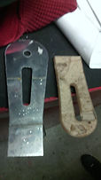
Left: The two plates after waterjet cutting. Middle: JB Weld lathered onto the extreme edges of the lap joint. Right: The link prior to testing
Left: The link after testing.
Right: Close-up of the aluminum loading hole where failure occured.
Team
-
Samson Chiu
-
Allistair Cota
